
Engineering guide · Precision manufacturing
CNC Machine Tools Guide: Types, Materials & Selection Tips
Learn what CNC machine tools do, how common cutters and turning tools differ, which materials and coatings improve performance, and how we select tooling for accurate, repeatable parts.
The right tool is not simply the sharpest tool in the cabinet. It is the tool whose geometry, material, coating, holder, and cutting conditions match the part, machine, and production goal.
What Are CNC Machine Tools?
CNC machine tools are the cutting, forming, drilling, turning, grinding, or electrical-discharge tools used by computer numerical control equipment to create a part. Examples include end mills, drills, inserts, boring bars, reamers, thread mills, grinding wheels, and EDM electrodes. Each tool converts programmed machine motion into a specific manufacturing operation.
It helps to distinguish the tool from the CNC machine. The machine provides the structure, spindle or workholding system, axes, coolant delivery, and controller. The tool is the replaceable or mounted cutting element that contacts the workpiece. A three-axis machining center, for example, may use an end mill to produce a pocket, a drill to create a hole, and a reamer to bring that hole to a more controlled final size.
The machine platform
Axes, spindle, controller, workholding, coolant, and enclosure coordinate the process and maintain tool position relative to the part.
The cutting tool
Flutes, edges, inserts, point geometry, and tool material determine how material is removed and how the resulting feature looks and measures.
In precision manufacturing, tooling is part of the engineering decision, not an afterthought. At PartsMake, we review the drawing, CAD geometry, material, tolerances, critical dimensions, surface requirements, and quantity before deciding how a part should be machined.
Common Types of CNC Machine Tools
Tool selection begins with the feature being produced. A flat face, deep cavity, cross-hole, internal bore, and thread all place different demands on geometry and rigidity. The following tools cover many everyday CNC machining workflows.
End Mills and Ball End Mills
End mills are rotating cutters used primarily in milling. Flat end mills can slot, pocket, contour, shoulder, and interpolate features. Their number of flutes affects chip space, rigidity, and suitable feed rates. A two- or three-flute design may provide more room for chips in some aluminum applications, while higher flute counts can support finishing or harder materials when the cutting conditions allow.
Ball end mills have a rounded tip and are useful for three-dimensional contours, molds, blends, and radiused surfaces. They are especially valuable in 3-axis and 5-axis work where the tool follows a curved surface. However, the center of a ball end mill has very low surface speed when it is cutting directly on the tip, so toolpath strategy and step-over matter greatly for surface quality.
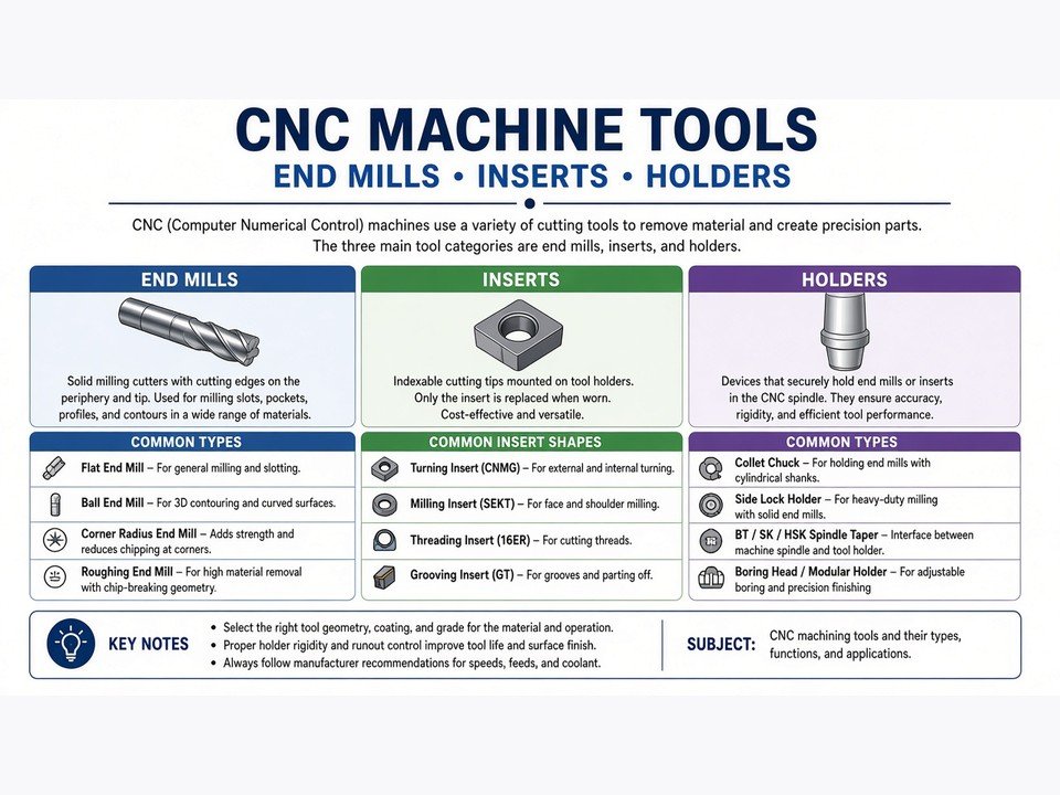
Milling tool geometry should be matched to the feature, material, depth, and required finish.
Drill Bits and Reamers
Drills create holes efficiently, but a drilled hole is not automatically a precision hole. Point angle, helix, flute design, coolant access, and chip evacuation influence hole quality. For deep holes, pecking or other controlled cycles may be required to clear chips and reduce heat.
Reamers remove a small amount of material after drilling to improve size consistency, roundness, and surface finish. They are finishing tools rather than general-purpose hole makers, so the pre-drilled diameter and alignment must already be suitable. When a drawing calls for a controlled bore, we also consider whether boring, interpolation, grinding, or another process is more appropriate than reaming alone.
Face Mills and Slab Mills
Face mills use multiple cutting edges around a broad diameter to remove material from the top of a workpiece. They are effective for creating a flat reference surface, reducing stock, and preparing a part for subsequent operations. Many face mills use replaceable inserts, allowing the cutting edges to be changed without replacing the complete body.
Slab mills are generally used for heavier material removal across a wider surface, often with horizontal milling arrangements. The distinction between tool families can vary by machine setup and supplier terminology, so the practical questions are cutting width, available spindle power, rigidity, stock allowance, and the flatness or finish requirement.
Turning Tools, Boring Bars, and Cut-Off Tools
Turning tools are used on lathes to remove material from a rotating workpiece. External turning tools reduce diameter, create shoulders, and generate tapers or profiles. Facing tools produce the end surface, while profiling tools follow a programmed contour. Replaceable inserts are common because they offer consistent geometry and quick indexing between operations.
Boring bars enlarge or finish an existing hole from the inside. Their main challenge is rigidity: a long, slender bar can deflect or vibrate, which affects size and surface finish. Cut-off or parting tools separate a finished component from bar stock and require careful control of tool projection, feed, chip evacuation, and support near the cut.
Practical consideration
For turned shafts, bushings, sleeves, and threaded parts, tool access and workholding can be as important as the insert grade. A stable setup reduces the temptation to compensate for vibration by slowing every operation.
Thread Mills, Taps, and Knurling Tools
Thread mills create internal or external threads by interpolating around the feature. They can be useful when a single tool must produce different thread diameters or when process control and tool access favor milling. If a thread mill breaks, it may also be easier to remove than a broken tap, depending on the application.
Taps form internal threads by cutting or displacing material as they advance axially. They can be highly efficient for repeated standard threads, but synchronization, alignment, lubrication, and chip form are important. Knurling tools create a patterned surface for grip or functional engagement by pressing or cutting a profile into the workpiece rather than removing material in the same way as a conventional turning insert.
Specialty Tools: T-Slot, Dovetail, Fly Cutters, and Gear Cutters
Specialty cutters are selected when a standard end mill cannot reach or form the required geometry. T-slot cutters produce the undercut used in machine tables and fixtures. Dovetail cutters create angled-sided slots and guides. Fly cutters use one or a small number of cutting edges to sweep across a surface, often producing a distinctive finish and a broad, flat cut.
Gear cutters are shaped for specific gear tooth forms and require careful matching between cutter geometry, gear standard, module or diametral pitch, and setup. These tools can be highly productive for dedicated features, but they should not be chosen solely from a visual resemblance to the profile. The drawing and functional requirements must govern the selection.
How CNC Machine Tools Work
A CNC tool works as part of a controlled system. The controller interprets programmed coordinates, feed rates, spindle speeds, tool changes, and machining cycles. The machine then moves the tool, the workpiece, or both along defined axes while the cutting edge removes material according to the toolpath.
Prepare the model and process plan
CAD geometry is translated into a manufacturing strategy that defines setups, datums, tools, operations, and inspection points.
Load and measure the tool
The tool is installed in a holder or station, and its length, diameter, orientation, and wear offsets are established for the control.
Cut with controlled motion
The controller coordinates axis movement and spindle rotation while the tool removes material in roughing, semi-finishing, drilling, threading, or finishing passes.
Verify the result
Critical dimensions, surface requirements, material, and other drawing criteria are checked so the finished part is ready for its intended assembly or use.
Accuracy depends on more than the nominal path. Tool runout, holder quality, machine condition, thermal behavior, workholding, tool deflection, chip evacuation, and tool wear all influence the result. That is why a robust process includes stable references, sensible tool engagement, measured offsets, and inspection feedback.
Classifications of CNC Machining Tools by Process
Grouping tools by process makes selection more practical. The same material may be machined with different tools depending on whether the objective is fast stock removal, a controlled bore, a cosmetic surface, or a complex profile.
CNC Milling and Routing Tools
Milling tools rotate while the machine controls movement relative to the workpiece. Common choices include flat end mills for pockets and shoulders, ball end mills for contours, face mills for broad surfaces, and specialty cutters for slots, undercuts, and gear forms. Routing tools are often used for sheet goods, plastics, composites, and other applications where high-speed peripheral cutting and chip clearance are central concerns.
For a deep cavity, we may combine a larger roughing tool for efficient stock removal with smaller tools for corners and a ball end mill for the final surfaces. This reduces finishing-tool load and makes the toolpath more predictable.
CNC Turning and Boring Tools
Turning tools are mounted on a tool post or turret while the workpiece rotates. External inserts handle diameter reduction and profiling; facing tools establish end surfaces; grooving and cut-off tools create narrow features or separate parts. Boring tools work internally and require particular attention to overhang and vibration.
Mill-turn machining combines rotating-tool milling with turning in one coordinated setup. It can reduce re-fixturing for complex cylindrical components, but the process plan must account for tool orientation, access, workholding, and the relationship between turning and milling datums.
CNC Drilling and Tapping Tools
Drilling tools create the initial hole, while reamers, boring tools, or interpolated milling may establish the final size and location. Taps produce internal threads, and thread mills create threads through controlled helical movement. The choice depends on thread standard, material, hole depth, tolerance, quantity, and the risk associated with tool breakage.
Design-to-process reminder
A hole callout should be interpreted together with its diameter tolerance, depth, thread specification, positional requirement, and surface or fit function. “Drill it” is not a complete process definition when the hole is a critical interface.
Additional Processes: Grinding, EDM, Laser, Plasma, and Broaching Tools
Not every feature is best made by conventional cutting. Grinding wheels are used for precision mating and wear surfaces where controlled material removal and finish are important. EDM uses electrical discharge rather than direct mechanical cutting, making wire EDM and sinker EDM useful for hardened materials and complex profiles.
Laser and plasma processes use concentrated energy to cut or shape suitable materials, particularly in sheet and plate applications. Broaching uses a tool with progressively higher teeth to produce internal or external profiles in a guided stroke. These processes have different tooling, fixtures, heat effects, and finish considerations, so process selection should begin with the part requirement rather than with a preferred tool category.
| Primary operation | Typical tool family | Typical objective |
|---|---|---|
| Milling | End mills, ball end mills, face mills | Pockets, contours, shoulders, planar surfaces |
| Turning | Turning inserts, grooving tools, cut-off tools | Diameters, faces, grooves, profiles |
| Holemaking | Drills, reamers, boring bars | Holes, bores, controlled fits |
| Threading | Taps, thread mills, threading inserts | Internal and external threads |
| Special processes | Grinding wheels, EDM electrodes, broaches | Hardened materials, precision surfaces, dedicated profiles |
Tool Materials and Coatings
Tool material affects hardness, toughness, heat resistance, wear behavior, and allowable cutting conditions. A coating can further change friction, oxidation resistance, and edge durability. There is no universally best combination; the workpiece material and operation determine the useful balance.
Common Tool Materials
High-speed steel
High-speed steel offers toughness and versatility and is used for drills, taps, and other tools where impact resistance or a relatively forgiving edge is valuable.
Cemented carbide
Carbide provides high hardness and wear resistance and is widely used for end mills, inserts, drills, and other production tooling. It is more sensitive to shock and poor setup rigidity than tougher materials.
Ceramics and advanced cutting materials
Ceramic and other advanced materials can support specialized high-temperature or difficult-material applications. They demand appropriate machine stability, cutting conditions, and application knowledge.
Common Tool Coatings and Their Benefits
Coatings are thin engineered layers applied to a tool surface. Depending on the coating system, they can reduce friction, limit adhesion between tool and workpiece, improve resistance to heat and oxidation, and slow abrasive wear. Common families include general-purpose hard coatings, aluminum-rich coatings for elevated-temperature performance, and specialized low-friction coatings for particular materials.
A coated tool can still fail if chip evacuation, tool holding, runout, or cutting parameters are wrong. We treat coating as one variable within the complete process rather than as a substitute for sound geometry and a stable setup.
Selection warning
Avoid selecting a coating from a catalog label alone. The useful comparison is tool life and process stability on the actual workpiece, with the actual coolant, engagement, machine rigidity, and required surface condition.
How to Choose the Right CNC Machine Tools
A reliable selection method starts with the part and works backward to the tool. The goal is not to maximize cutting speed in isolation. It is to achieve the required geometry, tolerance, finish, cycle time, and repeatability at an acceptable total cost.
Start with the workpiece material
Identify the alloy, plastic, composite, hardness, abrasiveness, and tendency to work-harden or generate long chips. Material behavior determines edge geometry, flute space, coating needs, and heat management.
Define the operation and feature
Separate roughing, finishing, drilling, reaming, boring, threading, slotting, and profiling requirements. Choose a tool that naturally suits the feature instead of forcing one cutter to do every job.
Check machine and holder compatibility
Confirm spindle capacity, speed range, available torque, axis travel, tool envelope, holder type, coolant delivery, and workholding. Tool diameter and length must fit both the geometry and the machine’s practical limits.
Match geometry to the target result
Consider flute count, helix, corner radius, point angle, insert shape, nose radius, tool overhang, and access. A small radius may reach a corner but can be less robust than a larger radius where the design allows it.
Balance performance with total cost
Compare purchase price, tool life, cycle time, changeover time, scrap risk, rework, and availability. The lowest-cost tool per piece may not be the tool with the lowest purchase price.
Plan inspection and tool-wear control
Decide which dimensions reveal tool wear or process drift. Critical dimensions should be verified according to the drawing and project requirements, not inferred only from machine coordinates.
A useful decision sequence
Material → feature → operation → access → machine and holder → tool geometry → cutting conditions → inspection method. If a tool choice cannot be explained through this sequence, it probably needs another review.
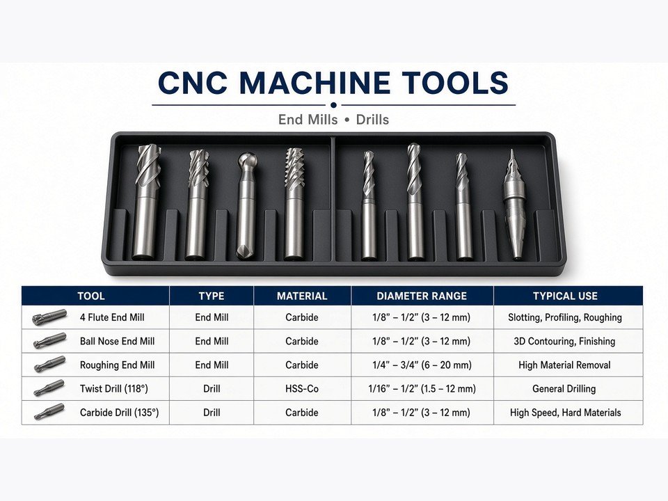
Machine compatibility includes tool access, workholding, spindle behavior, coolant, and the complete setup—not only the cutter diameter.
Is CNC Hard to Learn?
CNC is not effortless, but it is learnable. The difficulty comes from combining several disciplines: reading drawings, understanding coordinates and datums, selecting tools, setting work offsets, interpreting G-code or conversational programming, controlling feeds and speeds, and measuring the result.
A beginner does not need to master every process at once. We recommend starting with safe machine operation and measurement, then progressing through simple facing and pocketing, drilling, work offsets, tool offsets, simulation, and finally more complex multi-axis or mill-turn work. The habit of checking a toolpath before cutting is more valuable than memorizing isolated commands.
Core skills to build
Drawing interpretation, basic metrology, workholding, tooling, coordinate systems, CAM fundamentals, cutting conditions, and safe machine procedures.
Resources that reduce the barrier
Modern CAM simulation, controller graphics, structured training, technical tool documentation, and supervised shop practice make the learning process more visual and repeatable.
The fastest progress usually comes from connecting digital instructions to physical evidence: inspect the tool, observe the chips, listen for vibration, measure the feature, and relate the result back to the program and setup.
Is CNC Machinist a Dying Trade?
CNC automation changes the machinist’s work, but it does not remove the need for manufacturing judgment. Machines can repeat a programmed motion, yet people still need to decide how a part should be held, which process is practical, how a tool will reach a feature, how to respond to tool wear, and whether the measured part meets its requirements.
As shops adopt more automation, the valuable skill set expands toward process planning, CAM, inspection, setup reduction, troubleshooting, and communication with engineering and quality teams. Skilled machinists remain essential because real parts introduce variation that cannot be solved by a generic program alone.
Industry perspective
Automation is most effective when experienced people define a stable process. It handles repeatable motion well; machinists provide the practical reasoning that makes the process safe, manufacturable, and measurable.
At PartsMake, this engineering judgment supports work ranging from prototypes and engineering samples to pilot production, low-volume production, and repeat manufacturing. CNC machining is one capability within a broader process plan that may also include 5-axis machining, turning, Swiss machining, grinding, EDM, finishing, inspection, molding, sheet metal, or 3D printing.
FAQ
What is a CNC machine tool?
A CNC machine tool is the cutting or forming tool used by a computer-controlled machine to make a part. Examples include milling cutters, drills, reamers, turning inserts, boring bars, taps, thread mills, grinding wheels, and EDM electrodes.
What are the most common CNC machine tools?
End mills, ball end mills, drills, reamers, face mills, turning tools, boring bars, cut-off tools, taps, thread mills, and specialty cutters are among the most frequently used. The correct choice depends on the feature, material, machine, tolerance, and finish requirement.
Is CNC hard to learn?
CNC has a learning curve because it combines programming, tooling, machine setup, safety, drawings, and inspection. It becomes more accessible through structured training, simulation, controller graphics, and supervised practice on simple operations before advancing to complex work.
Is CNC machinist a dying trade?
No. Automation changes the role, but skilled machinists remain important for process planning, tool selection, setup, troubleshooting, measurement, and quality control. Modern machinists increasingly combine practical shop knowledge with CAM, inspection, and automation skills.
How do I choose a CNC tool for aluminum, steel, or plastic?
Begin with the exact material behavior, then match flute geometry, tool material, coating, rigidity, chip clearance, and cutting conditions to the operation. Aluminum may need efficient chip evacuation, steel may require a different balance of wear resistance and toughness, and plastics may require geometry that limits heat and avoids melting or tearing.
When should I use CNC machining instead of another process?
CNC machining is often a strong choice for precise metal or plastic components, prototypes, complex features, and low- to medium-volume work. The best process still depends on geometry, quantity, material, tolerances, finish, and cost; molding, sheet metal, grinding, EDM, or 3D printing may be better for specific requirements.
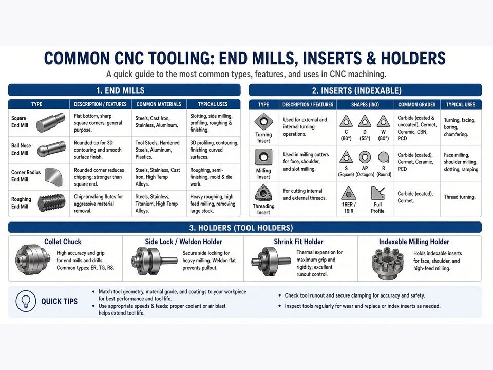
Tool selection is complete only when the finished feature is measured against the drawing and intended application.
Discuss your part with PartsMake
Need help choosing the right manufacturing process?
Send us your CAD files or drawings and project requirements. Our engineering team can review the material, critical dimensions, tolerances, surface needs, quantity, and intended application before production begins.