
Manufacturing Guide
CNC Prototype Machining: The Ultimate Guide to Rapid Product Development
How engineers turn a CAD file into a functional, testable, production-representative part — and where CNC prototype machining earns its place in a modern development cycle.
Introduction
CNC prototype machining is the practice of cutting a functional part directly from solid stock — aluminum, steel, brass, or an engineering plastic — using computer-controlled milling, turning, and multi-axis equipment. It is not a rough sketch in plastic. It is a real part, made from the material you intend to use in production, held to the tolerances your design actually requires. For engineers and product developers, that distinction matters more than almost anything else in the development cycle.
The shift we have watched over the past decade is not that CNC suddenly became new. It is that high-speed digital manufacturing collapsed the distance between a digital CAD file and a physical, testable object. Files travel instantly, CAM programming is faster, and quoting is often a matter of days rather than weeks. Where a first article once meant a long tooling commitment, a prototype can now be machined, measured, and revised inside a single iteration loop.
At PartsMake, our engineering team reviews drawings, CAD files, materials, tolerances, critical dimensions, and intended applications before production begins. That review is where most of the value of CNC prototyping is unlocked — not on the machine, but in the decision of what to machine, from what, and to what tolerance.
A prototype is not a model of your part. It is your part — made early enough to change your mind.
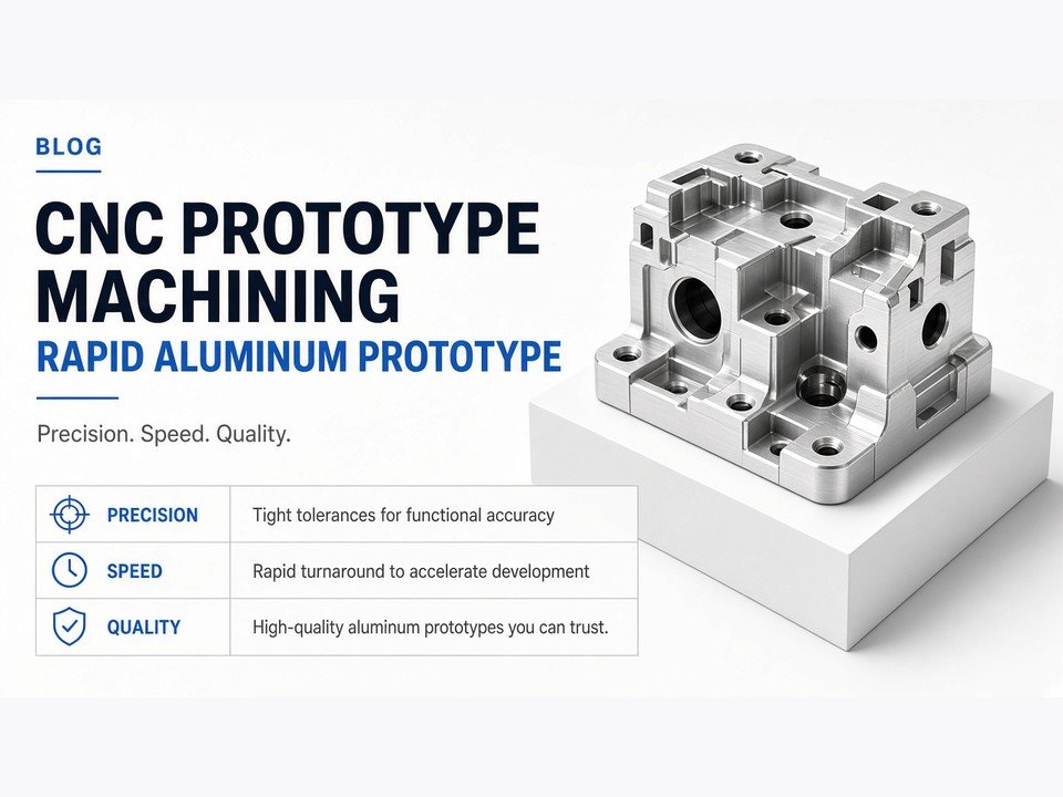
Why Choose CNC Machining for Prototyping?
There are four reasons we consistently see CNC prototype machining outperform alternative processes when the goal is to learn something real about a design. They are worth understanding individually, because each one solves a different problem.
Precision and Accuracy
CNC machining holds tolerances that additive processes generally cannot match on functional features. When a bearing must seat, a shaft must rotate freely, or two mating surfaces must seal, the geometry has to be right — not approximately right. Subtractive machining removes material under controlled conditions, so dimensions like bore diameters, flatness, and perpendicularity can be produced and verified directly.
This matters most at interfaces. A housing that is slightly oversized may still assemble; a housing that is slightly undersized may not. CNC lets you test the interface, not just the envelope.
Material Versatility
The strongest argument for CNC prototyping is that you can test with production-grade materials. Aluminum alloys, stainless and alloy steels, brass, copper, titanium, and a broad range of engineering plastics are all machinable. That means the stiffness, weight, thermal behavior, and corrosion resistance you measure on the prototype are the properties of the final part — not a stand-in.
When a design team has to substitute a printable resin for a machined aluminum bracket, they inherit a second, invisible variable: the material difference. CNC removes that variable.
Functional Testing
A prototype is only useful if it can be treated like the real thing. CNC parts withstand torque, clamping force, thermal cycling, and repeated assembly and disassembly in ways that many additive parts cannot. If your test plan involves a press fit, a threaded joint, a load path, or a heat soak, you want the prototype machined.
This is also how you catch failures early. A bracket that yields under load on the test bench is a bracket that would have failed in the field — and you found it before tooling.
Seamless Transition
The concept we call the bridge to production is simple: when the prototype and the production part are made by the same process, you carry fewer unknowns forward. The same material, the same tolerances, the same inspection criteria. CNC machining scales from one part to low-volume and repeat production without a process change, which means your validation work stays valid.
Why it matters
When prototype and production share a process, every test result transfers. When they do not, you are validating a proxy — and you will eventually have to re-validate the real part.
CNC Prototype Machining vs. 3D Printing
This is not a competition. Both processes are useful, and mature development teams use both — often on the same project. The question is which one answers the question you are currently asking.
Working Principle
CNC is subtractive: material is removed from a solid block by rotating cutters and turning tools. 3D printing is additive: material is deposited or fused layer by layer. Subtractive machining produces a continuous, homogeneous structure. Additive processes produce a layered structure with directional properties.
Material Support
CNC spans nearly the full range of engineering metals and plastics. Additive processes offer a narrower set of resins, nylons, and a growing but still limited range of metals. Where structural integrity matters, machined metal is usually the only honest option.
Geometric Complexity
This is where 3D printing genuinely wins. Internal channels, nested geometry, lattice structures, and organic shapes that would require multiple setups — or are simply unreachable by a cutter — print in one piece. Choose 3D printing when the geometry is the question. Choose CNC when the strength, tolerance, or material is the question.
Cost and Lead Time
For a single small, simple part, printing is often cheaper and faster. As parts grow in size, precision, and material cost, CNC becomes competitive and then clearly better. The table below reflects how we generally advise customers, though every project deserves its own review.
| Factor | CNC Prototype Machining | 3D Printing |
|---|---|---|
| Material range | Production-grade metals and engineering plastics | Resins, nylons, limited metals |
| Tolerance capability | Tight, verifiable on functional features | Looser, layer-dependent |
| Geometric freedom | Limited by tool access and setups | High — internal channels, lattices, organic shapes |
| Mechanical strength | Isotropic, production-representative | Directional, often lower |
| Best fit | Functional, load-bearing, precision parts | Concept models, complex geometry, early form checks |
Key Considerations for CNC Prototype Design (DFM)
Design for manufacturability is not a constraint on creativity. It is the fastest route to a part that works and a quote that makes sense. The following four areas account for most of the cost and risk we see in prototype designs.
Design for Manufacturability (DFM)
Every additional setup adds time, cost, and the risk of accumulated error. Design features so they can be reached from as few directions as possible. Where a feature can be added in a secondary operation that is simple and reliable, that is often cheaper than a complex single-setup approach.
Wall Thickness and Cavity Depth
Thin walls deflect under cutting force; deep cavities force long, slender tools that chatter and break. Both problems show up as poor surface finish, out-of-tolerance dimensions, and scrapped parts. Design generous walls and shallow pockets where you can, and flag the deep features so we can plan the tooling properly.
Corner Radii
Internal sharp corners are expensive because a rotating cutter always leaves a radius. If your design demands a sharp internal corner, it usually has to be cleared with EDM or hand work. Specifying a radius that matches a standard cutter removes that cost entirely and rarely affects function.
Standardization
Standard hole sizes and thread types lower cost because they use tooling already on the shelf. Specifying a metric or imperial thread that matches a common tap, or a bore diameter that matches a standard reamer, avoids special orders and setup delays.
DFM tip
Send the drawing and the CAD file together. The drawing tells us what matters; the CAD file tells us how to build it. When those two disagree, we will ask before cutting metal.
The CNC Prototype Machining Process
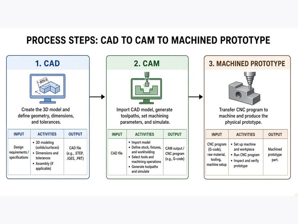
From a customer's perspective, a prototype order looks like a file going in and a part coming out. In practice there are five distinct stages, and each one is an opportunity to catch a problem before it becomes a scrapped part.
-
1
Step 1: CAD Design & File Preparation
We review the model for machinability — tool access, setups, and any features that will need special handling. If the geometry needs adjustment, we raise it before programming, not after cutting.
-
2
Step 2: Material Selection
Aluminum, steel, brass, or an engineering plastic — each choice affects strength, weight, machinability, finish, and cost. We help match the material to the function the part has to perform.
-
3
Step 3: Programming & Setup
CAM software converts the model into toolpaths. Tooling selection, workholding, and setup strategy are decided here — this is where most of the achievable precision is actually determined.
-
4
Step 4: Machining & Surface Finishing
The part is cut, then finished — anodizing, bead blasting, polishing, or a functional coating — depending on whether the finish is for appearance or for performance.
-
5
Step 5: Inspection & Quality Assurance
Critical dimensions are measured against the drawing. We verify what the design says matters, and we document the result so you can trust the part before you test it.
Industries Benefiting from Rapid CNC Prototyping
Different industries ask different questions of a prototype. What they share is a need for parts that behave like the final product.
Automotive & Aerospace
Prototypes here are tested for structural performance and weight reduction. Machined aluminum and steel parts let teams validate load paths, mounting geometry, and mass before committing to production tooling.
Medical Devices
High-precision components often require specific biocompatible or corrosion-resistant materials. CNC machining delivers the tight tolerances and material control these applications demand.
Consumer Electronics
Housings and internal components iterate quickly. Machined prototypes let teams test fit, finish, and assembly feel — the details that decide whether a product feels finished.
Industrial Robotics
Durable mechanical parts — brackets, joints, end effectors — need to survive real duty cycles. Machined prototypes are the only way to test that honestly before production.
How to Optimize Cost and Lead Time
Prototype budgets are real budgets. Three levers move the number more than anything else.
Batching
Combining multiple parts into one order amortizes setup time across the batch. If you have several revisions or a family of related parts, order them together.
Material Choice
Common, easily machinable alloys are cheaper and cut faster. If the prototype does not need a specialized material, a standard alloy will usually do the job and cost less.
Communication
Clear technical drawings and open communication with your machine shop eliminate the back-and-forth that eats lead time. Tell us what the part does and which dimensions are critical.
Frequently Asked Questions
How much does CNC prototyping cost?
Cost depends on four variables: material, geometry, volume, and urgency. A simple aluminum bracket and a complex multi-axis housing are not comparable. The most reliable way to get a real number is to send us the drawing and CAD file — we review it and quote against the actual part.
Is CNC a hard job?
It is skilled work. A prototype machinist or CNC programmer has to understand tooling, workholding, materials, and tolerance stack-up, and make judgment calls that software cannot. The programming is only part of it — the decisions around it are the craft.
Will CNC be replaced by AI?
AI is already helping with DFM analysis and automation of routine programming tasks, and that is a good thing. What it does not do is cut metal. The physical process — fixturing, cutting, measuring, and adjusting — still requires hands and judgment. We see AI as a tool that makes engineers and machinists faster, not a replacement for either.
What is a prototype machinist?
A prototype machinist specializes in low-volume, high-precision work — often one-off or small-batch parts where there is no room for a second attempt. The skill set combines programming, setup, tooling selection, and inspection, with a strong bias toward getting it right the first time.
Conclusion
CNC prototype machining is a strategic advantage, not just a manufacturing step. By producing functional parts in production-grade materials, it removes the guesswork from validation and shortens the distance between a design and a decision. The teams that treat prototyping as a real engineering activity — with proper DFM, material selection, and inspection — consistently reach market faster and with fewer surprises.
If you are evaluating your next project, start with the question you need answered. Is it strength? Tolerance? Fit? Thermal behavior? The answer will tell you whether to machine, print, or do both — and in what order.
Selecting a partner
Look for a manufacturer who reviews your file before quoting, asks about the application and critical dimensions, and can carry the same part from prototype through repeat production. That continuity is worth more than a marginally lower first quote.
Start your prototype
Send us your drawing and CAD file
Our engineering team reviews materials, tolerances, critical dimensions, surface requirements, and intended application before production begins. We identify manufacturing risks early, control quality throughout the process, and deliver parts that are ready for assembly and use — from prototype through repeat production.