
Stiffness of Materials Explained: Definition, Calculation, and Engineering Use
Deflection under load can compromise tight tolerances, lead to tool chatter, and cause catastrophic misalignment in precision assemblies. Here is how we evaluate, calculate, and design for the stiffness of materials across CNC machining, additive manufacturing, and structural engineering.
"A component can possess massive tensile strength without breaking, but if it flexes just a fraction of a millimeter too far, an entire kinematic drive, optical alignment, or high-speed machining spindle can seize."
What is Stiffness? Defining the Material Property
In mechanical and manufacturing engineering, stiffness refers to the ability of an object or material to resist elastic deformation under an applied mechanical force. When a workpiece or structural element is loaded, it experiences stress and consequently strains. If the material returns completely to its original dimensions when that load is removed, the response sits entirely within the elastic regime. Stiffness measures how steep that elastic barrier is.
Mathematically, structural stiffness ($k$) establishes the fundamental direct relationship between applied force ($F$) and resulting displacement ($\delta$):
In practical parts manufacturing at PartsMake, whether we are milling thin-walled aluminum aerospace enclosures or grinding tool-steel shafts, stiffness is what dictates positional repeatability and operational geometry under dynamic loads. Without sufficient stiffness, structural integrity degrades long before physical yield or rupture occurs.
The Core Difference: Stiffness vs. Strength vs. Hardness
When clients submit CAD models and 2D engineering drawings to us for technical review, one of the most frequent material specification missteps we observe is confusing stiffness with tensile strength or surface hardness. While related through material family characteristics, they represent distinct physical behaviors.
| Property | Primary Definition | Key Metric / Units | Engineering Concern |
|---|---|---|---|
| Stiffness | Resistance to elastic deflection under applied load. | Young's Modulus (GPa, Mpsi) | Component deflection, chatter, geometric tolerance drift. |
| Strength | Resistance to permanent plastic deformation or total rupture. | Yield / Tensile Strength (MPa, ksi) | Permanent bending, cracking, necking, catastrophic rupture. |
| Hardness | Resistance of a localized surface to penetration, scratching, or abrasion. | Rockwell (HRC), Vickers (HV), Brinell (HB) | Contact friction wear, galling, surface gouging, pin erosion. |
Material deflection curves reflect intrinsic elastic modulus independent of heat treatment temper.
Heat treating an alloy steel shaft from 30 HRC to 58 HRC nearly doubles its yield strength and drastically improves surface wear resistance, but its stiffness remains virtually unchanged at approximately 205–210 GPa. If your shaft deflects 0.05 mm under a side load before heat treatment, it will still deflect 0.05 mm after hardening.
The Science Behind Stiffness: Young’s Modulus Explained
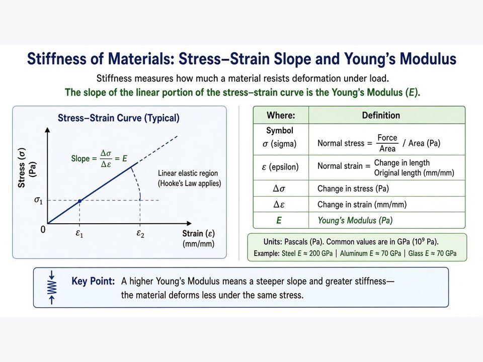
While structural stiffness depends on part geometry and supports, the intrinsic material property governing stiffness is the Modulus of Elasticity, commonly known as Young’s Modulus ($E$). In uniaxial tensile loading, Young’s Modulus represents the slope of the initial linear portion of the engineering stress-strain curve:
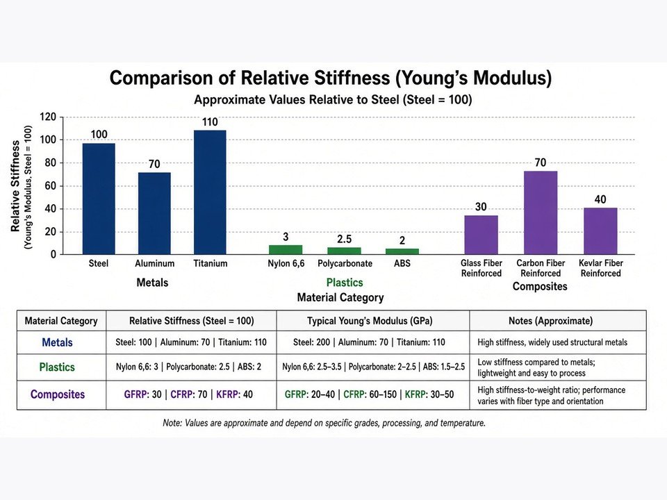
Within this hookean elastic window, atomic bonds are stretched like micro-springs without rearranging their crystalline lattice. When the applied stress is removed, the atoms return to their equilibrium interatomic spacing. Below is a comparative baseline of Young’s Modulus values for engineering materials frequently processed in our machining and fabrication facilities:
| Material Grade / Category | Young’s Modulus (GPa) | Density (g/cm³) | Specific Stiffness (E / ρ) |
|---|---|---|---|
| Tungsten Carbide (Cemented) | 550 – 650 | 14.5 – 15.0 | High (Extreme resistance) |
| Structural & Tool Steels (4140, 304, D2) | 190 – 215 | 7.85 | Standard benchmark (~26) |
| Titanium Alloy (Ti-6Al-4V Gr.5) | 110 – 115 | 4.43 | Balanced (~25) |
| Copper & Brass Alloys (C360, C110) | 100 – 125 | 8.5 – 8.9 | Low-to-Moderate |
| Aluminum Alloys (6061-T6, 7075-T6) | 69 – 72 | 2.70 – 2.81 | High efficiency (~25.5) |
| High-Performance Polymers (PEEK, POM/Delrin) | 3.0 – 4.2 | 1.3 – 1.4 | Compliant / Dampening |
Factors Influencing Material Stiffness
In an assembled machine, overall structural stiffness is a coupled equation involving both intrinsic material parameters and physical spatial architecture:
Atomic Bonding and Chemical Composition
Materials with strong covalent or metallic bonds have higher interatomic force constants, resulting in elevated elastic moduli. For example, carbon fiber filaments and ceramics exhibit exceptionally tight atomic spacing and rigid bond angles, providing high intrinsic modulus compared to the long, flexible hydrocarbon chains of standard thermoplastics.
Geometric Cross-Section & Second Moment of Area
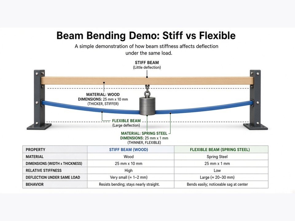
Bending resistance is heavily governed by the area moment of inertia ($I$). Distributing material further from the neutral bending axis (such as in I-beams, hollow structural rectangular tubing, and ribbed plate sections) dramatically boosts flexural stiffness without requiring a heavier or pricier material alloy.
Boundary Conditions and Structural Supports
How a part is clamped, pinned, or constrained drastically changes its apparent stiffness. A beam with both ends fixed (clamped-clamped) exhibits a deflection sixteen times smaller than an identical beam simply supported at both ends under a center point load. Rigidity is as much a function of the interface as the component itself.
Engineered rib patterns on CNC machined brackets optimize the second moment of area while minimizing mass.
Types of Stiffness in Structural Engineering
In mechanical assemblies, forces rarely act in single isolation. Depending on the vector and point of application, we categorize stiffness into four structural modes:
Tensile / Compressive Stiffness
The resistance against lengthening or shortening under collinear axial loads. Crucial for hydraulic cylinder tie rods, lead screws, and CNC column uprights where pull or push forces must not alter axial positioning.
Bending (Flexural) Stiffness
The product of Young's Modulus and the second moment of area ($E \cdot I$). Determines lateral deflection when a transverse load acts perpendicular to the part's longitudinal axis, such as gantry crossbeams and linear guide rails.
Torsional Stiffness
The resistance to angular twisting around the longitudinal axis under an applied torque ($G \cdot J$). Fundamental in high-precision drive shafts, servo couplings, and industrial robotics arm joints where angular backlash or lag induces positional tracking errors.
Rotational & Shear Stiffness
The capacity to resist angular displacement at pinned interfaces or transverse sliding across parallel cross-sectional planes, governed by the Shear Modulus ($G$). Essential for short, stocky brackets, shear pins, and kinematic mounts.
How to Calculate and Assess Stiffness
For pure axial tension or compression of a uniform prism bar, calculating stiffness ($k$) follows directly from basic mechanics of materials:
Where A is cross-sectional area, E is Young's Modulus, and L is original unsupported length. Notice that doubling the length cuts the axial stiffness in half, while doubling the cross-sectional area doubles it.
Methods for Engineering Assessment
1. Quasistatic Elastic Modulus Testing (Tensile / 3-Point Bend)
Standardized coupons (ASTM E8 for metals, ASTM D638 for polymers) are pulled in precision load frames with extensometers to map the true elastic region, ensuring exact values are fed into downstream modeling.
2. Dynamic Mechanical Analysis (DMA)
For polymer and composite parts, stiffness varies significantly across temperature and operating frequency. DMA separates storage modulus (elastic return) from loss modulus (viscous dampening), preventing thermal creep deflection failures in real-world environments.
3. Finite Element Analysis (FEA) Simulation
For non-uniform geometries like multi-axis robotic arms or complex engine brackets, analytical closed-form equations fail. FEA discretizes complex meshes to calculate static deflections, natural resonance modes, and localized compliance under multi-directional loading conditions.
FEA displacement plots allow engineers to pinpoint compliant zones and optimize rib locations prior to cutting metal.
Best Practices: Designing for Stiffness
In high-precision manufacturing, we follow a disciplined design process to achieve target structural rigidity without adding unnecessary weight or driving up machining cycle times:
In optical mounts, precision coordinate-measuring machine (CMM) fixtures, CNC spindle housings, and semiconductor wafer-handling end effectors, stress levels rarely reach 15% of material yield strength. Designing strictly for strength yields parts that flex excessively, ruining positioning. In these assemblies, stiffness governs every dimensional decision.
Frequently Asked Questions
What is an example of an exceptionally stiff material?
Tungsten carbide and technical ceramics like silicon carbide and alumina exhibit extraordinary stiffness, with elastic moduli spanning 400 to 650 GPa—roughly two to three times that of structural carbon steel. On the other end of the spectrum, elastomers such as silicone and polyurethane feature moduli under 0.05 GPa, yielding orders of magnitude more under slight pressure.
How can I increase the stiffness of a design without changing the material?
You can increase stiffness geometrically by expanding the moment of inertia in the direction of load: adding web ribs, switching solid rods to larger-diameter hollow tubes, short-coupling cantilevered spans, or shifting from single-shear pinned joints to double-shear fixed clamp bosses.
Why does stiffness matter in real-world industrial applications?
In robotics and aerospace, flexure introduces structural vibration, tracking hysteresis, and reduced natural frequencies, forcing control systems to operate slower. In automotive drivetrains and machining centers, insufficient stiffness induces gear misalignment, premature bearing failure, and severe surface finish chatter marks.
Conclusion
Understanding the stiffness of materials is essential to bridging the gap between theoretical CAD models and reliable, functional production hardware. While yield strength protects a part against permanent failure, stiffness ensures it executes its operational function within tight physical tolerances.
By analyzing cross-sectional moments of inertia, selecting materials with the right specific stiffness, and verifying deflections through simulation, engineers can balance material raw cost, part weight, and structural rigidity. At PartsMake, our engineering team reviews your drawings, tolerances, and service conditions to recommend the optimal alloy and manufacturing method from prototype through volume production.
Optimize Your Parts for Stiffness and Manufacturability
Have critical tolerances, deflecting assemblies, or demanding material specifications? Submit your CAD models and drawings for a comprehensive manufacturing and DFM review with our engineering team.