
Engineering guide · Precision manufacturing
Types of Fits in Engineering: Clearance, Transition & Interference Explained
Learn how clearance, transition, and interference fits control the relationship between mating parts—and how to select the right tolerance system for reliable assembly, movement, and service life.
A fit is not simply a dimension on a drawing. It is the controlled relationship between two manufactured surfaces, designed around movement, assembly force, load, temperature, and service conditions.
What Are Engineering Fits and Tolerances?
In mechanical engineering, a fit describes how two mating features—usually a hole and a shaft—relate after manufacturing. The relationship determines whether the shaft can move freely, must be pressed into the hole, or may fall into either condition depending on the actual produced dimensions.
A tolerance is the permitted variation around a nominal dimension. No machining or forming process produces every part at exactly the nominal size. For example, a nominal 20 mm shaft may be accepted within a specified upper and lower limit, while the mating hole receives its own limits. The fit is created by comparing those limits—not by considering either feature in isolation.
Nominal size
The reference dimension used to identify the feature, such as 25 mm. It is the starting point for calculating limits, not necessarily the dimension that every finished part will measure.
Limits and tolerance
The upper and lower permissible sizes define the manufacturing window. The difference between those limits is the total tolerance available to the process.
Understanding the different types of fits and tolerances matters because an unsuitable fit can create friction, looseness, assembly damage, noise, leakage, or premature wear. At PartsMake, we review fit-related dimensions together with material, surface finish, process capability, inspection method, and intended application before production begins.
Design note
A fit callout should communicate the functional requirement. If a shaft must rotate, a designer should define the required running relationship rather than simply asking for a “tight” or “loose” fit.
The Three Main Types of Fits
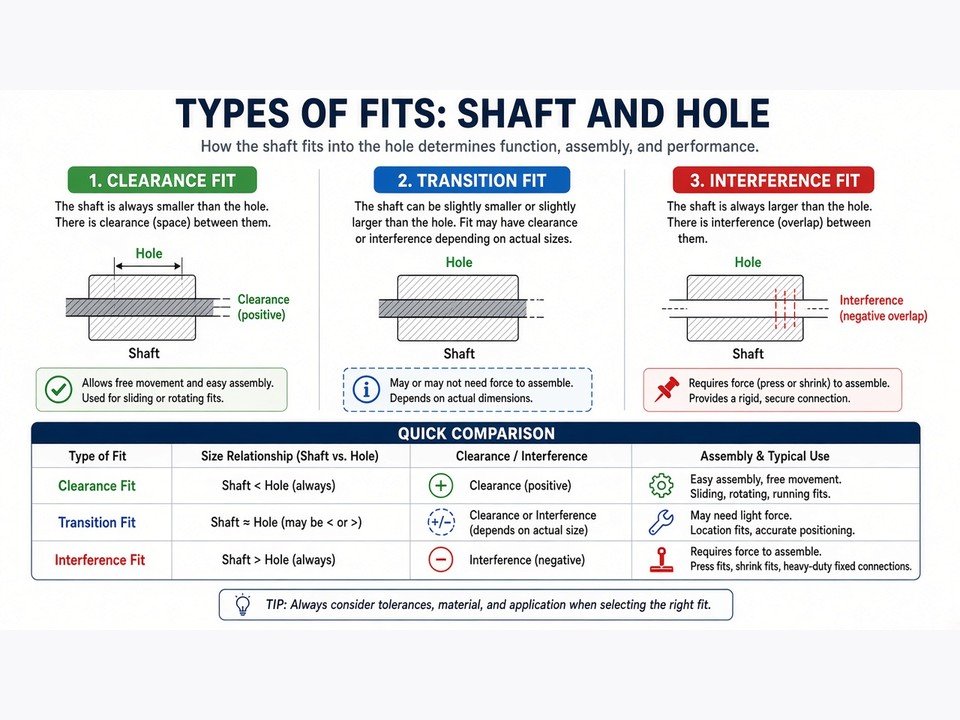
The three fundamental types of fits are clearance fits, transition fits, and interference fits. They are distinguished by the possible relationship between the largest shaft and the smallest hole, and between the smallest shaft and the largest hole.
| Fit type | Defining relationship | Typical purpose |
|---|---|---|
| Clearance | The hole is always larger than the shaft. | Free movement, sliding, rotation, or easy assembly. |
| Transition | The actual result may be clearance or slight interference. | Accurate location with controlled assembly. |
| Interference | The shaft is always larger than the hole. | Permanent retention and load transfer. |
Clearance Fits
A clearance fit guarantees space between the mating surfaces. The minimum clearance is calculated from the smallest hole minus the largest shaft. The maximum clearance is calculated from the largest hole minus the smallest shaft. Both values are positive in a true clearance fit.
The amount of clearance depends on the required motion, the part size, surface finish, lubricant, operating temperature, and the accuracy needed. A generous clearance may support contamination or thermal expansion, while a smaller clearance can improve guidance and reduce unwanted play.
Running and sliding clearance
Running fits are selected for relative motion, such as a rotating shaft, while sliding fits allow one component to move axially. The fit must account for lubrication and heat generated during operation.
Locational clearance
A locational clearance fit provides easy assembly while retaining better positional control than a loose running fit. It is useful where parts are removed during maintenance.
Common applications include shafts in plain bushings, removable covers, guide pins, sliding carriages, bearing-related assemblies, and parts that must be installed by hand. Clearance fits are also helpful when thermal growth could otherwise turn a nominally close fit into an interference condition.
Transition Fits
A transition fit sits between clearance and interference. Depending on the actual dimensions produced for the hole and shaft, the assembled parts may have a small clearance or a small interference. This makes transition fits useful when accurate location is important but the assembly should not require a heavy press operation.
The designer should decide how the parts will be assembled and inspected before choosing a transition fit. If a particular assembly must always have clearance, a clearance fit is more appropriate. If any separation under service load would be unacceptable, an interference fit may be required.
Where transition fits help
We commonly think of transition fits for precision locating features, removable hubs, dowel arrangements, and assemblies where concentricity matters but the parts may need to be separated during service.
Typical subtypes are often described as locational transition or close transition fits. The exact designation depends on the selected standard and size range. In aerospace, robotics, semiconductor equipment, and other precision assemblies, this fit category can balance repeatable positioning with manageable assembly force.
Interference Fits
An interference fit guarantees that the shaft is larger than the hole across the specified limits. The minimum interference is the smallest shaft minus the largest hole. The maximum interference is the largest shaft minus the smallest hole. Both values are positive when expressed as interference.
Because the mating parts overlap dimensionally, assembly produces contact pressure and elastic deformation. Depending on the size, material, and interference amount, the joint may be assembled with a press, by heating the surrounding component, by cooling the inserted component, or through a combined method.
Interference-fit example
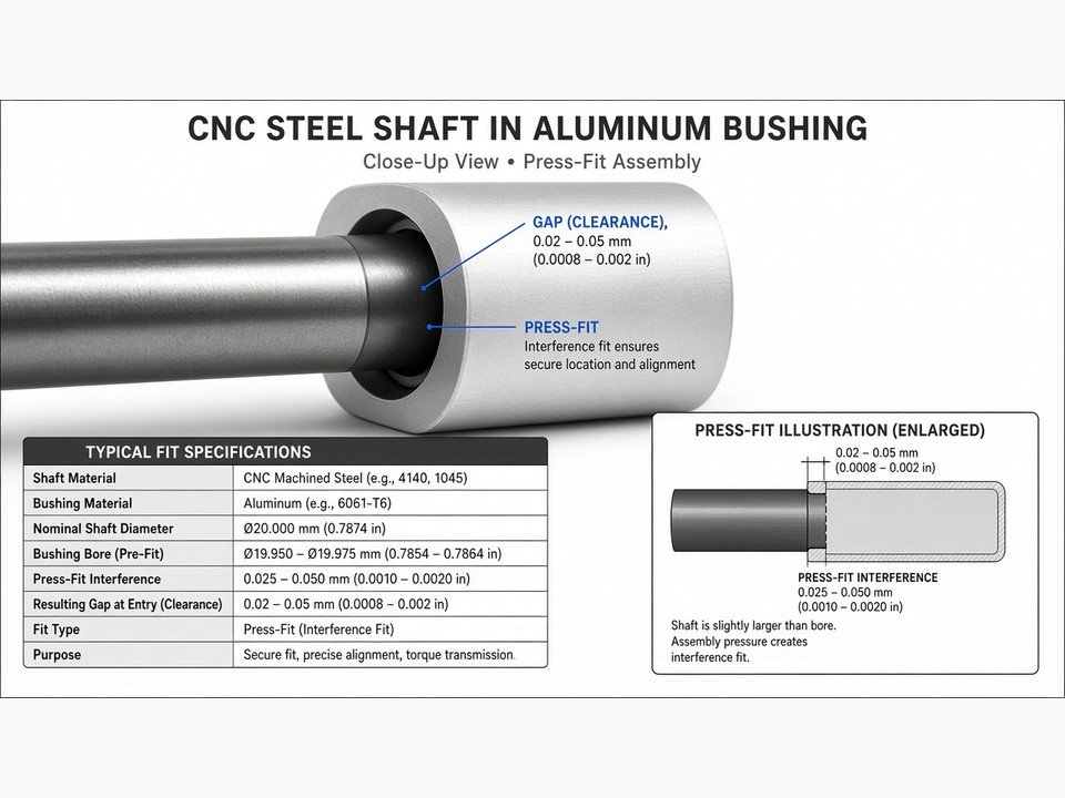
Suppose a steel shaft is specified from 20.010 mm to 20.020 mm, while the mating hole is specified from 19.990 mm to 20.000 mm. The minimum interference is 0.010 mm, and the maximum interference is 0.030 mm.
This relationship could be used to retain a hub on a shaft or install a bushing that should not rotate in its housing. The final design still needs verification for material strength, wall thickness, assembly force, temperature, and the required service load.
Common interference-fit subtypes include press fits, drive fits, and force fits. Their practical use ranges from permanent bushings and gear hubs to bearing rings, rotors, pins, and high-load structural joints. Excessive interference can deform a part, damage a surface, reduce fatigue life, or make assembly impossible, so the fit must be calculated rather than chosen by intuition.
Mating surfaces must be considered as a system: size, form, finish, material, and assembly method all influence the result.
Hole Basis vs Shaft Basis Systems
Fit systems can be organized around either a standard hole or a standard shaft. This choice determines which feature remains at a basic deviation and which feature receives the adjustment to create the desired clearance, transition, or interference.
| System | How it works | Practical advantage |
|---|---|---|
| Hole basis | The hole uses a common basic position, and the shaft tolerance position changes to produce the selected fit. | Works well with standard drills, reamers, and bore sizes. |
| Shaft basis | The shaft uses a common basic position, and the hole tolerance position changes to produce the selected fit. | Useful when shafts, bars, pins, or other external features are standardized. |
The hole-basis system is widely convenient because hole-making tools and standard bearing or bushing dimensions often drive the design. The shaft-basis system can be sensible when one shaft must mate with several components or when the shaft is produced by a process with a fixed standard size.
Neither system is universally better. We select the basis by considering the manufacturing process, available tooling, standard components, inspection strategy, and whether the design includes multiple mating parts.
Tolerance Grades and Designations
An engineering fit designation usually combines a tolerance position with a tolerance grade. In the ISO system, capital letters generally identify holes and lowercase letters identify shafts. The letter indicates the location of the tolerance zone relative to the basic size; the number indicates the IT grade, or degree of tolerance width.
Lower IT numbers represent tighter tolerance zones, while higher numbers represent wider zones. The actual permitted width also depends on the nominal size range. Therefore, a designation should always be interpreted with its standard and size range rather than treated as a universal numerical value.
What H7 means
“H” identifies the hole tolerance position, and “7” identifies the IT7 grade. For an H hole, the lower deviation is positioned at the basic size in the applicable ISO system; the upper limit is above it by the grade-specific tolerance.
Pairing the designations
A complete fit callout pairs the hole and shaft designations, such as an H7 hole with a selected shaft tolerance. The resulting pair—not H7 by itself—determines whether the fit is clearance, transition, or interference.
For example, a hole callout may be paired with a shaft designation chosen for easy sliding, accurate location, or press assembly. The same H7 hole can therefore participate in different fit types depending on the shaft zone selected.
Drawing discipline
Avoid specifying a tolerance grade without defining the mating feature and functional relationship. A production drawing should make the hole-shaft pair, datum scheme, surface requirement, and inspection expectation clear.
ISO and ANSI Fit Standards
ISO and ANSI-based systems both provide structured ways to specify limits, fits, and tolerance classes, but their designations and reference tables are not interchangeable without checking the applicable standard. The standard named on the drawing should guide calculation, manufacturing, and inspection.
| Reference approach | Typical designation logic | What to verify |
|---|---|---|
| ISO limits and fits | Hole and shaft tolerance positions use letters, with IT grades defining tolerance magnitude. | Nominal size range, standard edition, hole/shaft basis, and complete paired callout. |
| ANSI/ASME practice | Limits and fits may be communicated through inch or metric limits, tolerance classes, and standardized fit designations. | Unit system, applicable ANSI/ASME standard, class definition, and whether limits are unilateral or bilateral. |
ISO fit designations such as H7 are frequently used on metric drawings. ANSI/ASME documentation may use different class terminology or tabulated limits, especially in inch-based work. In both cases, the engineering intent remains the same: establish controlled upper and lower limits that produce the required mating relationship.
At PartsMake, we do not infer a critical fit from an isolated number when the drawing standard is unclear. We raise technical questions early so the dimensions can be manufactured and inspected against the intended reference.
How to Choose the Right Engineering Fit
Selecting among the types of fits starts with the function of the joint, not with a preferred tolerance symbol. I recommend reviewing the following questions before finalizing a drawing.
-
1
What must the joint do?
Define whether the parts rotate, slide, locate, transmit torque, resist separation, or remain permanently assembled.
-
2
What operating conditions apply?
Consider temperature changes, lubrication, contamination, vibration, pressure, load direction, corrosion, and expected wear.
-
3
How will assembly happen?
Identify hand assembly, press assembly, thermal assembly, adhesive assistance, disassembly requirements, and available tooling.
-
4
How will the fit be verified?
Choose measurement methods appropriate to the tolerance, feature geometry, surface finish, and production quantity.
For freely moving shafts and guides, start with a clearance-fit analysis. For accurate removable positioning, evaluate a transition fit. For hubs, permanent bushings, or joints carrying substantial load, evaluate interference—but check stresses and assembly force before committing.
Material pairing is also important. Dissimilar materials can expand at different rates, and softer materials may deform during pressing. Surface roughness, roundness, cylindricity, and edge conditions can affect real assembly behavior even when the size measurements are within tolerance.
Manufacturing review
A technically correct fit can still be difficult to manufacture if the tolerance is tighter than the process or inspection plan supports. We review critical dimensions, material, finish, quantity, and intended use together before recommending a production approach.
Real-World Applications and Examples
The best fit depends on the job the assembly must perform. The following examples show how the three categories appear in practical engineering work.
Moving machinery
A shaft rotating in a bushing generally needs controlled clearance for movement and lubrication. A sliding carriage may use a different clearance level to balance guidance accuracy with the risk of binding.
Permanent assemblies
A bushing installed into a housing or a hub mounted on a shaft may use an interference fit to prevent relative motion. Assembly force and material deformation must be checked before production.
Precision locating
A transition fit can locate a removable component accurately while avoiding the high assembly force associated with a stronger press fit. This can suit precision fixtures and serviceable equipment.
High-load components
Interference fits can transfer load through contact pressure in hubs, rotors, pins, and other components. The design must account for fatigue, wall thickness, temperature, and the possibility of assembly damage.
Inspection confirms the produced limits and helps connect drawing requirements to actual assembly performance.
These applications appear across robotics and automation, automotive and EV systems, aerospace and drones, semiconductor equipment, electronics, medical and laboratory equipment, and general industrial machinery. PartsMake supports these projects from prototype and engineering samples through pilot and repeat production, coordinating machining, grinding, finishing, inspection, and other required processes as appropriate.
Frequently Asked Questions About Types of Fits
What are different types of fits?
The three main types are clearance fits, transition fits, and interference fits. A clearance fit always leaves space between the mating parts, a transition fit may produce either slight clearance or slight interference, and an interference fit always creates an overlapping dimensional relationship.
What is a H7 tolerance fit?
H7 is a hole tolerance designation in the ISO limits and fits system. “H” identifies the position of the hole tolerance zone, while “7” identifies the IT tolerance grade. H7 alone does not define a complete fit; it must be paired with a shaft designation and interpreted for the applicable nominal size.
What are the different types of fits and tolerances?
The principal fit categories are clearance, transition, and interference. Tolerances define the permitted size variation that creates those relationships. Tolerance systems may use hole-basis or shaft-basis arrangements, ISO IT grades, ANSI/ASME classes, unilateral limits, bilateral limits, or other drawing conventions depending on the selected standard.
Can you give me an example of an interference fit?
If a shaft measures between 20.010 mm and 20.020 mm and its mating hole measures between 19.990 mm and 20.000 mm, the assembly has 0.010 mm minimum interference and 0.030 mm maximum interference. A design like this could retain a hub or bushing, provided the materials, wall thickness, assembly process, and service loads are suitable.
Need help validating a fit before production?
Send us your drawing or CAD data and tell us how the parts will move, assemble, and operate. Our engineering team can review the fit callout alongside material, tolerance, surface requirements, manufacturing process, and inspection needs.
Discuss your parts with PartsMake