
Types of Milling Operations: Complete Guide to Machining Techniques
From basic facing passes to 5-axis simultaneous contouring, selecting the correct milling operation directly affects surface finish, tool life, and manufacturing cost. As application engineers at PartsMake, we break down every core technique used in modern precision CNC machine shops.
On This Page ▾
PartsMake Engineering Note
At PartsMake, manufacturing starts with understanding the part—not simply turning on a spindle. Milling encompasses dozens of distinct kinematic cuts. Choosing the wrong operation leads to tool deflection, chatter, surface roughness out of tolerance, and excessive cycle times.
What Is Milling and How Does the Process Work?
Milling is a subtractive machining process where material is removed from a stationary or moving workpiece using a rotating cutting tool with multiple cutting edges (teeth). Unlike CNC turning, where the raw stock rotates against a single-point stationary tool, milling relies on high-speed cutter rotation combined with multi-axis feed movements along the X, Y, and Z axes (and rotational A, B, or C axes in 4-axis and 5-axis machines).
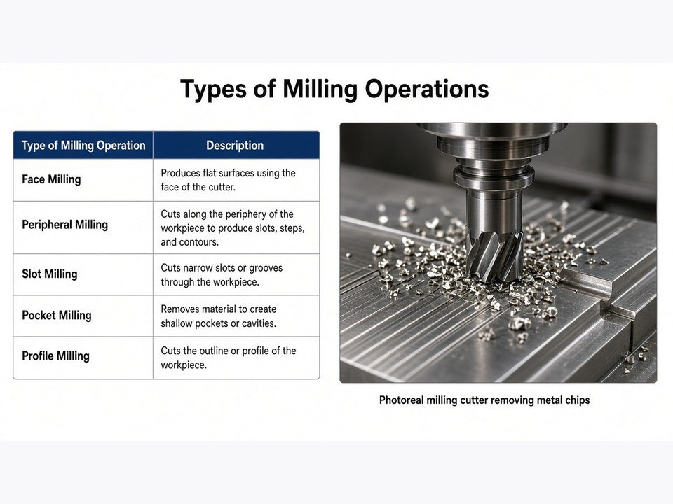
Multi-tooth end mill removing material along programmed toolpaths during a high-speed milling cycle.
The fundamental cutting mechanism relies on chip formation: as each cutting tooth enters the raw material, it shears off a micro-slice called a chip. Three primary machine components govern this interaction:
Machine Spindle
Holds the tool holder (BT30, BT40, HSK, or CAT) and delivers cutting torque and rotational speed (RPM) to drive teeth through stock.
Worktable & Fixture
Positions the stock securely via hydraulic vises, vacuum chucks, or custom zero-point clamping fixtures to absorb cutting forces without shifting.
Axis Feed Drives
High-precision ball screws and linear motors drive the relative linear motion between the rotating tool and workpiece at programmed feed rates.
How Many Types of Milling Operations Exist?
In modern manufacturing, there are over 15 distinct types of milling operations. Rather than memorizing an arbitrary list, machinists and mechanical engineers categorize them under two primary industrial classification systems:
1. By Workpiece Feature & Geometry
Classified by the shape, orientation, and kinematic path generated on the part:
- Face Milling & Plain (Slab) Milling
- End Milling, Pocketing, and Slotting
- Side, Straddle, and Gang Milling
- Form, Angle, CAM, Thread, and Gear Milling
2. By Cutting Kinematics & Control
Classified by how the tool interfaces with the material and the drive mechanism:
- Climb Milling (Down Milling) vs Conventional Milling (Up Milling)
- Manual Bridgeport-style vs 3-, 4-, and 5-Axis CNC Milling
- High-Speed Machining (HSM) vs Plunge/Trochoidal Milling
Types of Milling Operations by Workpiece Geometry
When our CAD/CAM programmers review your STEP files at PartsMake, we break down part features into specific toolpath operations. Here is how each geometry-driven operation works on the shop floor.
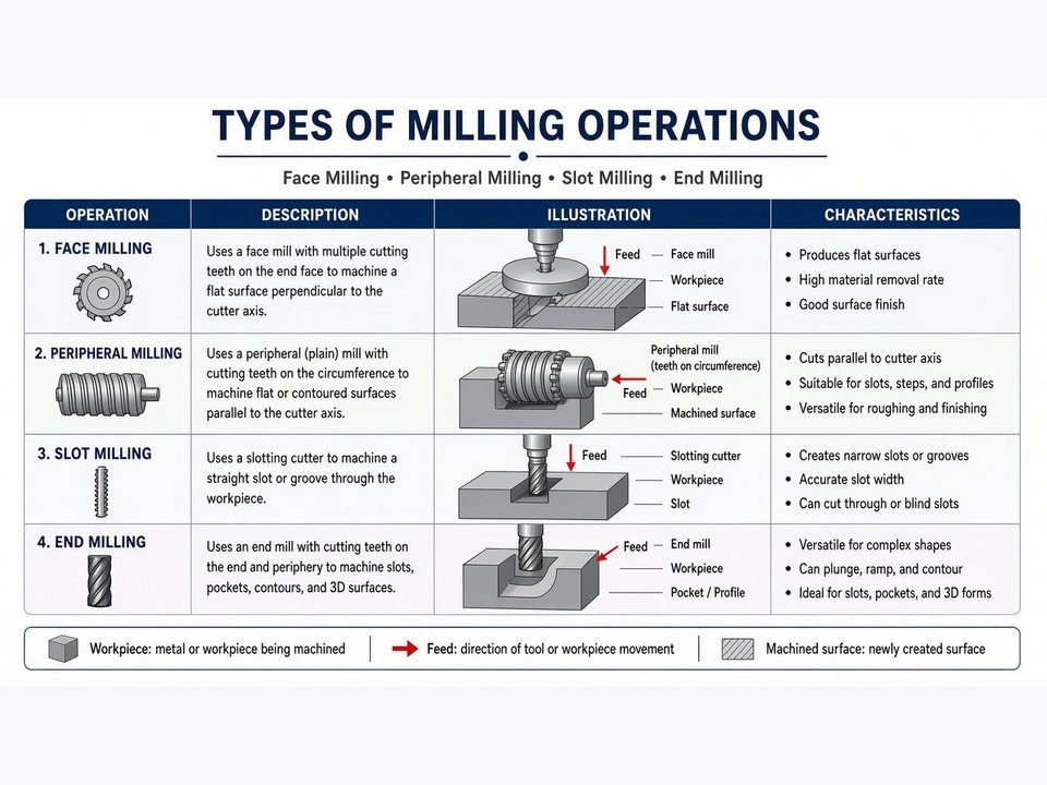
Face Milling
Face milling is used to produce flat, reference surfaces perpendicular to the spindle axis. The cutting action takes place predominantly on the peripheral face inserts, while the bottom corner of the inserts cleans up the finished surface. Indexable face mills with diameters ranging from 40 mm to 160 mm are commonly used to face large aluminum plates, gearbox split faces, and machine beds.
Machining Tip: Use a face mill diameter that is roughly 1.3 to 1.6 times the workpiece width. Positioning the cutter off-center prevents simultaneous entry of inserts on opposite sides, minimizing high-frequency chatter and vibration.
Plain (Slab) Milling
In plain milling (also called slab milling), the cutter's axis of rotation is parallel to the surface being machined. This operation is typically performed on horizontal milling machines using cylindrical cutters mounted on an arbor. Slab mills feature cutting teeth on their outer perimeter only. Helical-tooth slab mills are preferred over straight-tooth variants because the gradual tooth engagement drastically smooths cutting forces across broad surfaces.
End Milling and Slot Milling
End milling is the most versatile operation in CNC machining. Solid carbide end mills feature cutting teeth both on their cylindrical periphery and flat end face. This dual capability allows end mills to plunge, interpolate pockets, step-cut 2D contours, and mill precise blind or through-slots.
Slot milling cuts closed channels, T-slots, or keyways. When machining closed slots without pre-drilled pilot holes, center-cutting end mills or ramped entry toolpaths are mandatory to prevent cutter breakage.
End milling contouring internal pockets and structural ribs on a 5-axis machining center.
Side, Straddle, and Gang Milling
These three related operations are high-efficiency techniques often utilized on horizontal arbors or multi-spindle equipment:
Side Milling
Machines vertical flat surfaces on the side of a part using cutting teeth on both the perimeter and outer side face.
Straddle Milling
Mounts two side milling cutters on the same horizontal arbor, spaced by precision shims, to machine two parallel surfaces in a single pass.
Gang Milling
Combines three or more diverse cutters (e.g., slab mills, side cutters, and form cutters) on one arbor to cut an entire complex profile simultaneously.
Angle, Form, and Gear Milling
Special geometry often demands cutters with pre-formed ground profiles:
- Angle Milling: Uses single-angle or double-angle cutters to mill chamfers, bevels, and dovetail slide ways at specific angles (typically 45°, 60°, or 75°).
- Form Milling: Generates concave or convex radii, corner-rounding beads, and complex custom contours using ground cutters matching the finished part profile.
- Gear Milling: Employs involute gear cutters matched to tooth counts and diametral pitch, indexing the workpiece tooth by tooth on a dividing head or 4th rotary axis.
Thread, Saw, and CAM Milling
Thread Milling: Unlike rigid tapping, CNC thread milling uses a helical interpolation toolpath where the cutter rotates and spirals axially along the Z-axis. It is the gold standard for blind holes in tough alloys (Inconel, Titanium) because broken taps are eliminated and pitch diameter can be precisely adjusted via tool offsets.
Saw Milling (Slitting): Employs narrow circular slitting saws to part off stock, separate machined segments, or mill thin thermal relief slots.
CAM Milling: Produces cylindrical, barrel, or disc cams. In CNC setups, 4th and 5th rotary axes interpolate continuously with the X/Y linear feeds to produce smooth, non-linear acceleration profiles for automated cam tracks.
Types of Milling Operations by Mechanism and Control
Beyond the final shape of the component, milling processes are defined by tool engagement kinematics and machine motion control.
Manual vs CNC Milling
While manual knee mills (such as Bridgeport machines) remain invaluable in toolrooms for quick facing, squaring stock, and secondary deburring, CNC (Computer Numerical Control) dominates modern production. Modern 3-axis, 4-axis, and 5-axis CNC machining centers run automated G-code with linear optical scales yielding positional repeatability within ±0.005 mm (±0.0002 in).
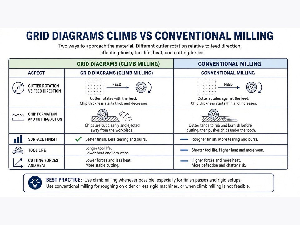
Conventional Milling vs Climb Milling
Every machinist must choose between climb milling and conventional milling. The physics of chip formation directly affects surface roughness, tool deflection, and spindle load:
| Parameter | Climb Milling (Down Milling) | Conventional Milling (Up Milling) |
|---|---|---|
| Feed Direction | Workpiece moves in the same direction as cutter rotation | Workpiece moves against cutter rotation |
| Chip Thickness | Maximum at entry, thins to zero at exit | Zero at entry, thickens to maximum at exit |
| Surface Finish | Superior; minimal rubbing or burnishing | Rougher; tool rubs during initial tooth entry |
| Tool Life | Longer; heat escapes into the thicker chip | Shorter due to friction and work hardening |
| Machine Requirement | Rigid CNC machines with preloaded ballscrews | Legacy manual machines with backlash |
| Best Used For | CNC finishing, roughing non-crusted alloys | Cast iron crust, forge scale, heavy manual cuts |
Engineering Rule of Thumb
In CNC milling centers, we default to climb milling in 95% of operations because it directs cutting forces downward into the fixture and delivers Ra 0.8 μm (32 μin) or better surface finishes. We only switch to conventional milling when dealing with raw casting scale or abrasive hard skins that would prematurely chip inserts upon entry.
Types of Milling Cutters and Tools
Successful milling depends on pairing the geometry with the correct tool geometry. Here are the 13 most common milling cutters utilized across precision machine shops:
Standard solid carbide and indexable milling cutters organized by geometry and flute count.
How to Choose the Right Milling Operation
Selecting the best milling approach involves four technical engineering factors:
Workpiece Material & Hardness
Aluminum 6061-T6 permits aggressive 2-to-3-flute end milling with peripheral speeds over 400 m/min. In contrast, Titanium Grade 5 (Ti-6Al-4V) or hardened D2 tool steel requires multi-flute carbide tools with TiAlN/AlCrN coatings, low surface speeds, and trochoidal dynamic toolpaths to manage cutting heat.
Geometric Complexity & Access
Prismatic parts with orthogonal step faces are efficiently machined on 3-axis CNCs using standard face and end milling. For deep pockets, undercut ports, or sculptured organic profiles, 5-axis positional or simultaneous milling prevents excessive tool stickout, chatter, and multiple re-clamping setups.
Tolerance and Surface Texture Target
Separating roughing and finishing passes is non-negotiable. Roughing leaves 0.25 mm (0.010 in) of stock. Finishing uses high-speed climb milling or wiper insert face mills to achieve tight dimensional tolerance (±0.01 mm) and smooth cosmetic textures.
Batch Size and Machine Parameters
One-off prototypes prioritize standard tooling from the tool crib to avoid specialty cutter expenses. High-volume repeat runs justify gang milling, custom form tools, or dedicated multi-station fixtures to drive down cycle time.
Frequently Asked Questions
What are the types of milling operations?
The primary types of milling operations include face milling, plain (slab) milling, end milling, slot milling, side milling, straddle milling, gang milling, angle milling, form milling, gear milling, thread milling, and slitting (saw milling). They can be run under either climb or conventional milling kinematics.
How many types of milling are there?
There are roughly 15 recognized milling operations in industrial practice. When categorized broadly, they fall into two basic families: peripheral milling (where the tool axis is parallel to the machined surface) and face milling (where the tool axis is perpendicular to the machined surface).
What are the 13 different types of milling cutters?
The 13 most common milling cutters are: flat square end mills, ball nose end mills, bull nose (corner radius) mills, indexable face mills, roughing end mills, slab mills, side & face cutters, T-slot cutters, Woodruff keyseat cutters, dovetail cutters, chamfer mills, thread mills, and slitting saws.
What are different types of machining operations?
Milling is one branch of traditional subtractive machining. The other primary machining operations are turning (on CNC lathes), drilling, boring, reaming, shaping/planing, broaching, precision grinding (surface, cylindrical, centerless), and non-traditional methods like Wire EDM and Sinker EDM.
Optimize Your CNC Milling Project with PartsMake
Need high-precision milled prototypes or volume production runs? Send us your CAD drawings (STEP, IGES, DXF, or PDF). Our engineering team performs a thorough DFM review before cutting metal to ensure tight tolerances, fast turnaround, and cost-efficient machining.